Pipe stress analysis you can see all the way through.
SWBPIPE · free and open source
A program for piping flexibility and stress analysis, with an agent built in that works in the model beside you. Learn the method, try the alternative, and understand the answer before you hand it on.
MIT licence · macOS · signs in with ChatGPT
Chapter I
Ask it why.
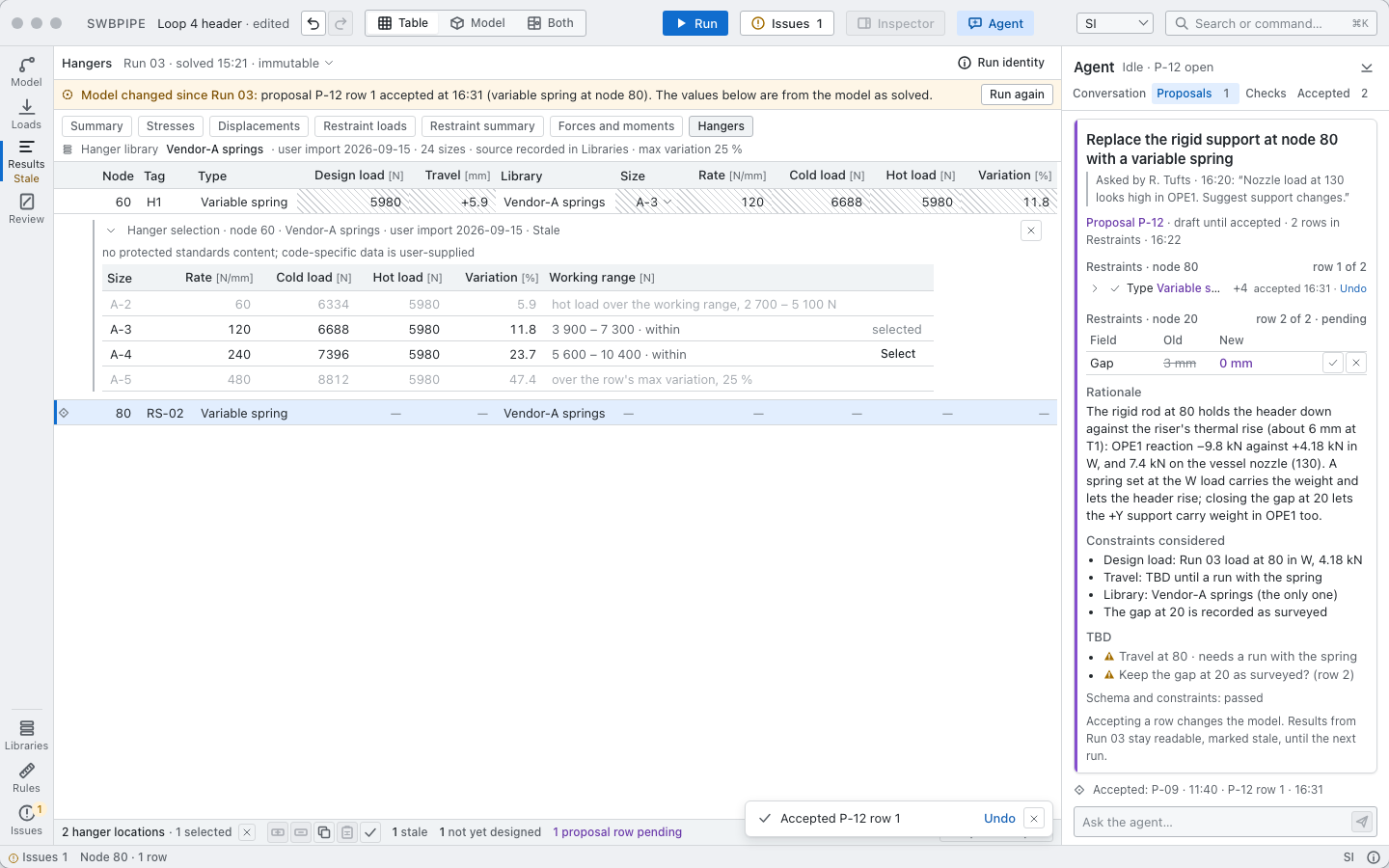
The nozzle load at 130 looks high. You say so. The agent reads the model and the last run, and finds what a senior engineer would: the rigid rod at 80 is holding the header down against the riser’s thermal rise.
It proposes a variable spring in its place, shows its reasoning and what it still does not know, and waits. You accept the change a row at a time and run again.
The agent is there to widen what you can see, not to see for you.
Chapter II
Nothing is hidden.
Every part of the answer can be opened and read, by you or by the agent on your behalf.
2.1The model is a table.
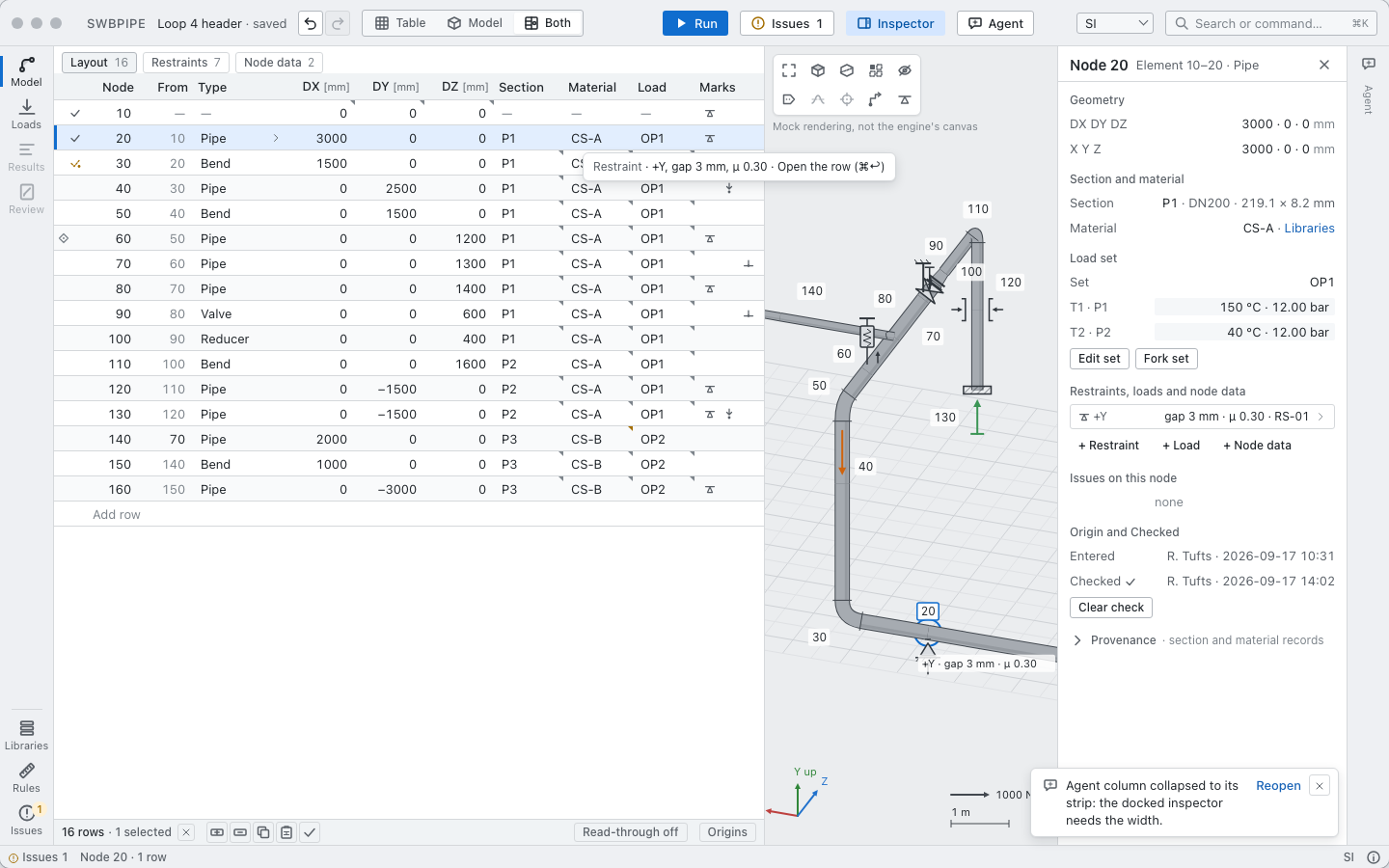
One row per node, the way stress engineers have always written a system down. The drawing is made from the rows, so what you see is what you entered.
2.2The mechanics are open.
A 3D frame solver with bends, nonlinear supports and load-case algebra. Read any line of it. Sixty-four benchmark cases are published with the hand calculations they are checked against.
2.3The agent can do what you can.
Build a system from a line list, place supports, run a case, trace a result back to the element and the equation behind it. Nothing it does enters the model until you accept it.
Chapter III
Your code, your data.
SWBPIPE ships with no code tables.
Allowables, stress intensification factors, load combinations and component data come from the standards and catalogues you already have the right to use, held in a rule pack you build. A guide and a template show you how.
The Chirality workflows built into SWBPIPE let the agent help you turn your own spreadsheets and data sheets into rule packs and libraries, and keep them current as your sources change. What you build stays yours, as files on your machine.
Chapter IV
Design on every desk. Validate on one.
SWBPIPE does not judge compliance with any code, and it does not vouch for the accuracy of its results. It is for learning, designing and exploring alternatives. Do not use it as the basis for professional work.
When a design needs validation, export it and validate it in the solver your industry accepts. In the first release that means a .mbf model batch file for CAEPIPE. More formats will follow.
Route, support, iterate and learn, as many people as need it, at no cost.
One seat validates the design your team settled on, under your engineer’s judgement.
The name
Named for Shipman, Watts and Burrows.
In 1941 the M. W. Kellogg Company published a general method for the stresses, reactions and deflections of a piping system in space.
Its acknowledgment credits W. H. Shipman, who first solved the single-plane problem systematically, and G. W. Watts and W. R. Burrows of Standard Oil (Indiana), who extended his method to three planes.
“The most significant step towards the general solution.” Design of Piping Systems, 1941, on Watts and Burrows
For decades engineers learned that method by hand, and the ones who knew it best went on teaching it long after they retired. The standards the industry relies on today were built by people like them, one careful detail at a time. SWBPIPE is made to keep that knowledge in the open: the method, the mechanics and every detail within reach of anyone willing to learn it.